Acciones posibles en una sesión de edición
Introducción
Editing commands are the set of orders used to edit or modify a drawing. More specifically, they cover all the processes and mechanisms required to modify and work with what has already been drawn.
gvSIG uses three different ways to run these commands.
- By clicking on the corresponding button from the tool bar.
- From the menu bar.
- By writing the command in the command console.
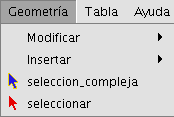
Seleccionar
Selección simple
To select one of the drawn objects in the layer we are editing, click on the "Select" button in the tool bar,

or go to the “Geometry” menu bar and then to “Select”.
Then click on the object you wish to select.
Selección compleja
You can access this button in the tool bar,

or by going to the “Geometry” menu bar then to “Complex selection”.
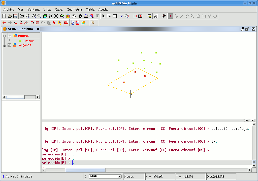
When the “Complex selection” tool has been selected, right click on the mouse in the graphic area. The following contextual menu will appear.
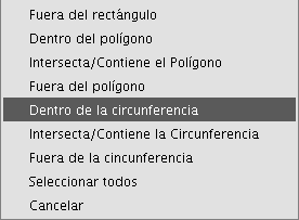
Click on the option you wish to use to select the elements.
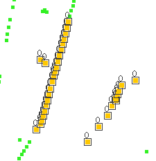
If you use the “Inside circle” option you can delimit a circle so that the elements you wish to select remain inside this area.
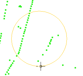
The selection result corresponds to the following image.
You can also write the “select” and “complex selection” commands in the command console. Command: “select” Write the command “select” in the command console.
When a message appears in the command console requesting you to add the selection point, input the coordinates of the object you wish to select.
If there is an object in the defined coordinates, it will be selected.

Command: “complex selection” Write the command “complex selection” in the command console and when the selection options appear, write the desired option.
The options are shown with their names, and in square brackets ([]) the text you need to input in the command console to use the option.

If, for example, you wish to select the features that are in a polygon area, you need to write “complex selection” in the command console, press “Enter” and then select the “IP” option.
This allows us to indicate the coordinates of the vertices which will make up the polygon (when the coordinates of each of the vertices are indicated a polygon is drawn in the drawing window) and when it is finished, the elements which are inside it are selected so you can work on them.
The following image shows how a selection option is input.

The following figure shows the definition of the selection polygon in the graphic area.
When the polygon is finished, the elements contained inside it will be selected so you can work on them.
- Selection options
- Outside rectangle [OR]: This allows you to delimit a rectangular area and select the elements which lie outside this area.
- Inside polygon [IP]: This allows you to draw a polygon area and select the elements located inside this area.
- Intersects with/Contains polygon [CP]: This allows you to draw a polygon area and select all the elements located inside it or which intersect with its perimeter.
- Outside polygon [OP]: This allows you to delimit a polygon area and select the elements which lie outside it.
- Inside circle [IC]: This allows you to delimit a circle and select all the elements located inside this area.
- Intersects with/Contains circle [CC]: This allows you to delimit a circle and select all the elements located inside it or which intersect with its perimeter.
- Outside circle [OC]: This allows you to delimit a circle and select the elements which lie outside it.
- Select all: This selects all the elements contained in the layer regardless of where they lie in it.
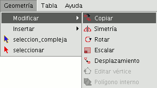
Copiar
This makes a copy of the objects you have selected. The elements copied will keep the same size and orientation as the originals. To access this tool, click on the “Copy” button in the tool bar

or go to the “Geometry” menu bar, then to "Modify" and "Copy".
The copying process is basically the same as the move process but the source objects do not move from their initial positions. New objects are created in the new location which are identical to the originals in size, shape and in the distance between them.
To make a copy, when the objects to be copied have been designated, two points need to indicated, the base point and the move point.
As with the rest of the tools, a projection of these objects will be shown in the view to specify the view location the copied objects are to be inserted in.
When the copied objects are situated in their location, click on the view again to set their position.
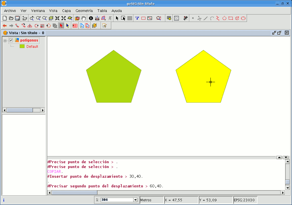
To copy objects from the command console, write the command "copy" when you have selected the objects you wish to copy, input the first move point and then the second point.
For example, when the command and the first move point have been input (30,40), the projection of the figure being copied appears. Input the second move point, (60, 40 in the example), and the new identical element will appear in the defined location.
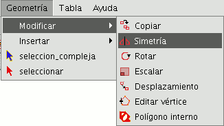
Simetría
This tool allows you to make a drawing which is symmetrical to the selected one. You can access this tool by clicking on the “Symmetry” button in the tool bar

or by going to the “Geometry” menu bar, then to “Modify” and “Symmetry”.
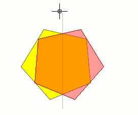
To obtain a symmetrical drawing in gvSIG, firstly select the element and then select the “Symmetry” option. Then, click on the display graphic area to insert the first symmetry axis point. gvSIG will then create a red projection of a figure which is symmetrical to the selected figure. You can then input the second point the symmetry axis will pass through by clicking on the graphic area again.
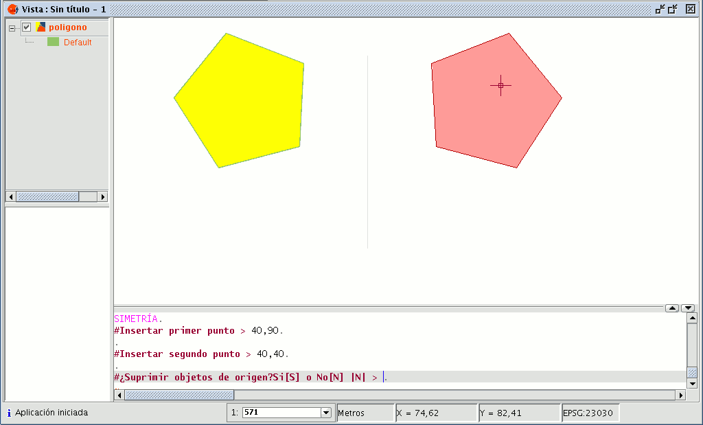
If you wish to run the tool from the command line, firstly write the command “symmetry”.
Input the first point the symmetry axis will pass through and press “Enter”. The console will then ask you to input a second point this axis has to pass through.
Input the point and press “Enter” again.
The console will ask you if you wish to keep the source object, write “Y” if you wish to keep it and “N” if you do not.
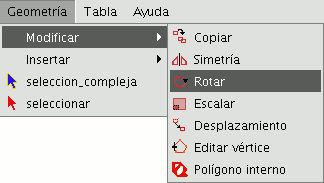
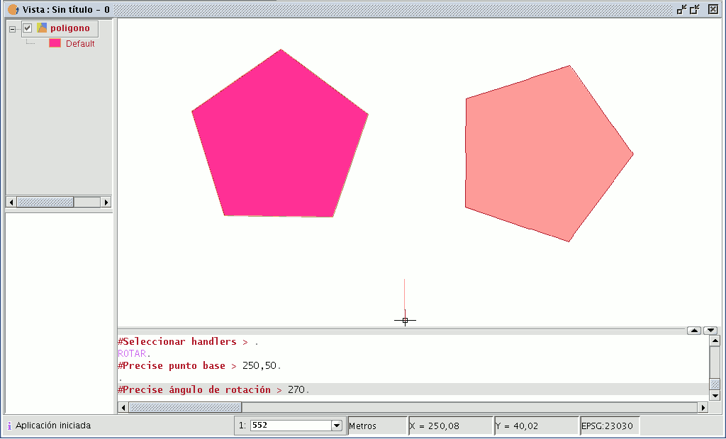
Rotar
You can use this tool to rotate the selected objects by taking a base point as the centre. You can activate this tool by clicking on the “Rotate” button in the edition tool bar

or by going to the "Geometry" menu bar, then to “Modify” and “Rotate”.
To rotate an element, first place the base point by clicking on the graphic area. Move the mouse, with the help of the projection that gvSIG uses to the effect, until the new position has been established.
Left click on the mouse in the view to define this point.
If you wish to rotate an element from the command console, select the object to be rotated, write the command “rotate” and input the first move point.
Then input how much you wish to rotate it in sexagesimal degrees.
The object will be rotated clockwise if you write a negative angle and anti-clockwise if you write a positive angle.
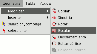
Escalar
This command can be used to modify the size of the selected objects. Select this tool by clicking on the “Scale” button in the tool bar

or by going to the "Geometry" menu bar then to "Modify" and “Scale”.
There are two ways of scaling, either by indicating a scale factor or by reference. Scaling by “Scale factor” To graphically scale elements using a scale factor, select the objects whose size you wish to modify, activate the scale tool and set the base point. The application will create an image which will give you a reference point about the size of the objects you are modifying.
As you get closer to the point you have set as the base point, the elements you are working with will get smaller, whilst the farther away you move, the bigger they will get.
When the objects are the desired size, click on the drawing window again. The same scale factor is applied for both the X and Y coordinates.
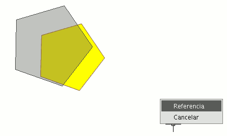
To graphically scale using the "Reference" option, select the objects and activate the “scale” command, then right click on the mouse inside the graphic area to show the tool’s contextual menu.
Select the “Reference” option. Indicate the points on the reference line and on the scale line as the messages in the command console are shown.
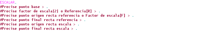
You can also use the “scale” command in the command console. When you have selected the objects to be scaled, write the command “scale” and then input the base point as shown in the following figure.
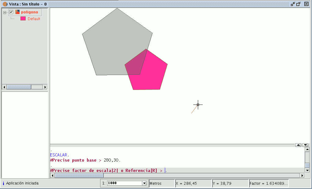
To increase the size of the objects you must input a scale factor which is greater than 1.
If you wish to reduce the size of the objects, the scale factor must be between 0 and 1.
If no value is input, gvSIG will use the scale factor 2 by default.
Scaling by “Reference” If you wish to scale using the "Reference" option, select the elements you wish to scale, choose the base point, then input the letter "r" into the command console to indicate that scaling by reference will be used.
Specify the source point and the final point of the reference straight line and then input the source point and final point of the scale line.
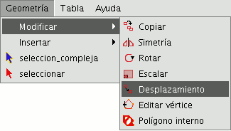
Desplazamiento
This tool allows you to move the selected objects from one point to another in the view by indicating a move vector. You can use this tool by selecting it from the tool bar by clicking on the "Move" button

or by going to the “Geometry” menu bar, then to “Modify” and "Move".
If you wish to move an element, select the object you wish to move and then activate the “Move” option. Click on the graphic area to define the move point.
gvSIG will create a red projection of the elements it is moving which can be used as a guide to position them in their new location.
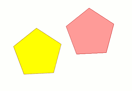
When the element is located in the desired position, left click on the mouse again to define the new position.
To use the “move” command from the command console, write the command “move”. The console will show a message requesting a move point. Input the point.
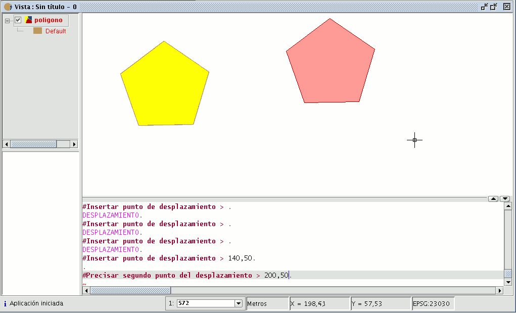
Then input the second move point. Press “Enter” and the object will move to its new position.
Editar vértice
This tool allows you to go through the vertices of the selected objects easily and carry out other actions, such as adding a new vertex or deleting the vertex which is being edited.
To access this tool, click on the “Edit vertex” button in the tool bar.

You can also access the tool by going to the “Geometry” menu bar then to “Modify” and “Edit vertex”.
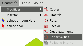
To edit the vertices of a figure, select the figure and click on the “Edit vertex” button in the tool bar.
A red pointer appears in one of the vertices of the figure you are editing.
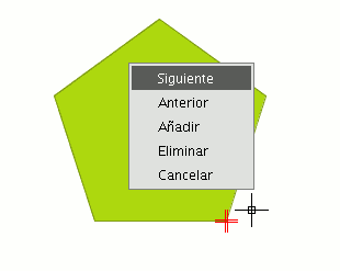
If you right click on the mouse, a menu will appear from which you can select the actions you wish to carry out.
If you click on the “Next” option, the cursor will move to the next vertex of the selected object.
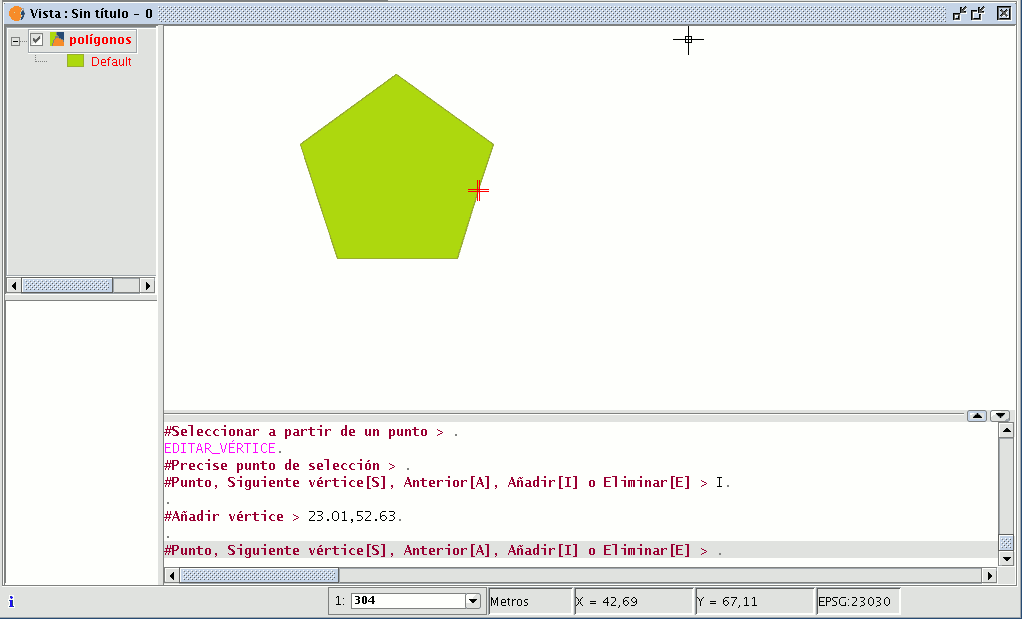
You can also access this tool from the command console. To do so, write the command: EDIT VERTEX.
If, for example, you wish to go through the vertices of an element, write the command and input the parameter “S” (next).
To go to the previous vertex, write the parameter “A”.
To delete a vertex write the parameter “E” and press “Enter”.
To add (insert) a vertex, write the parameter “I” and press “Enter”.
The X and Y coordinates of the new vertex will then be requested (remember that these coordinates should belong to the polygon perimeter).
Input the data in the console and press “Enter”.
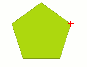
A new vertex will be created in the figure.
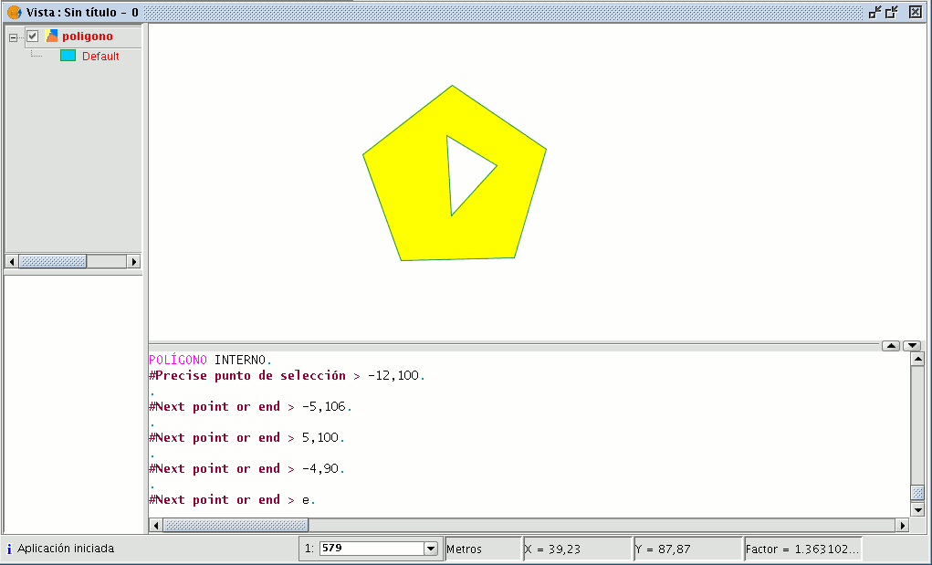
Polígono interno
This tool allows you to create a polygonal feature inside an existing feature.
You can access this tool by going to the "Geometry" menu then to "Modify" and "Internal polygon”
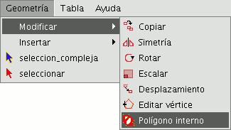
or from the following tool bar button:

You can create an internal polygon, either graphically or from the gvSIG command console.
If you wish to create the polygon graphically, the polygon element layer must be in editing mode and you must select the polygon on which you wish to use the selected tool.
Activate the "Internal polygon" tool and place the cursor where you wish to insert the first vertex.
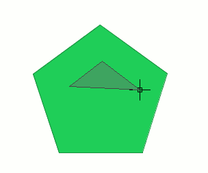
Then insert the vertices of the polygonal feature you wish to create. When you do not wish to insert any more vertices, right click on the mouse and select “End” from the contextual menu that appears.
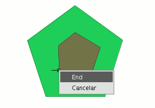
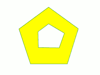
The corresponding internal polygon is created.
You can also use this tool from the command console. To do so, write the command “internal polygon” in the command line.
Then input the X and Y coordinates of the points which will correspond to the vertices of the new polygonal feature. When you have finished, write “e” to close the new internal polygon you have created.